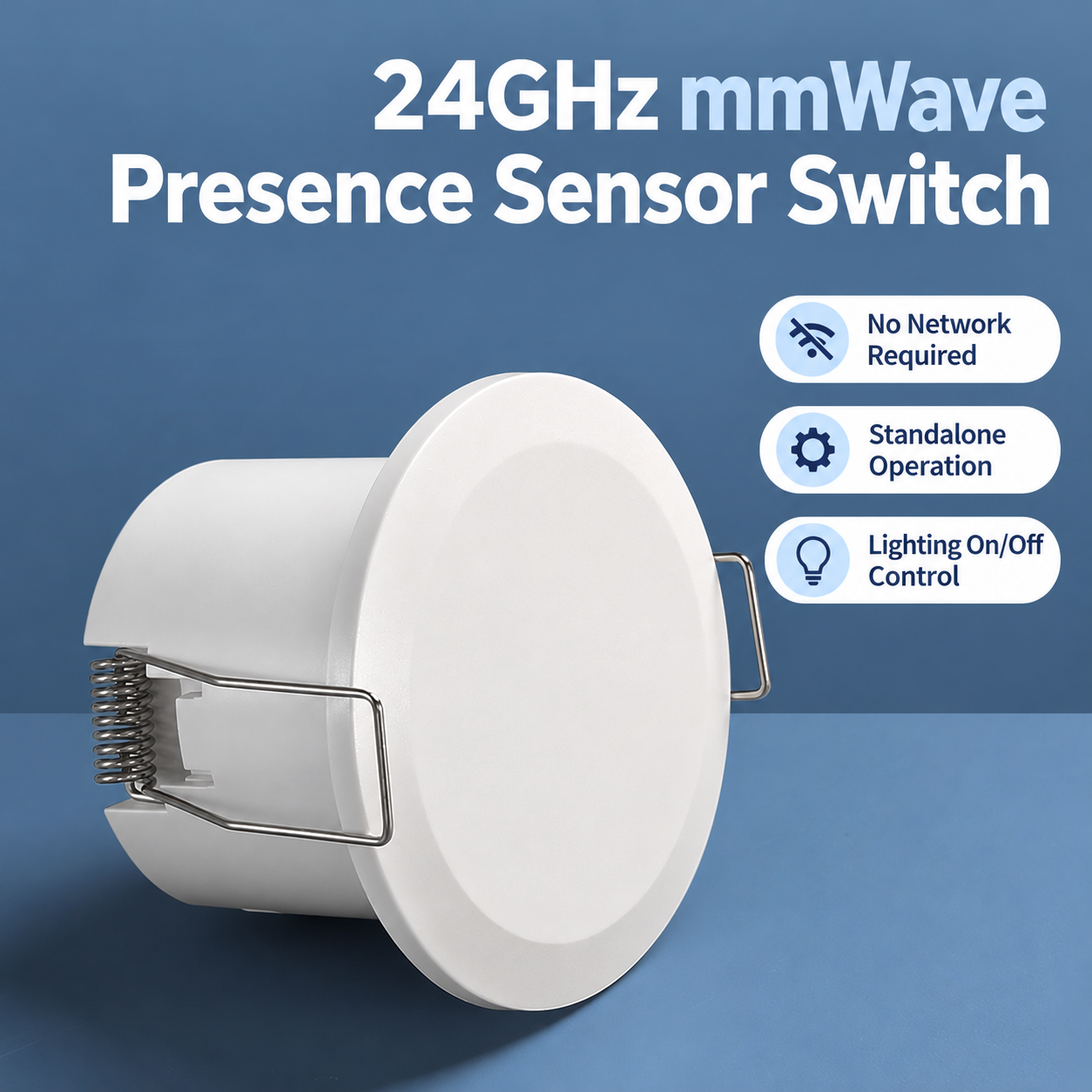
Control indoor lighting automatically with the 24GHz mmWave Presence Sensor Switch. This standalone recessed sensor detects movement and small body movements to support occupancy-based lighting control. No Wi-Fi, app or network connection is required.
Automatic Lighting That Responds to Occupancy
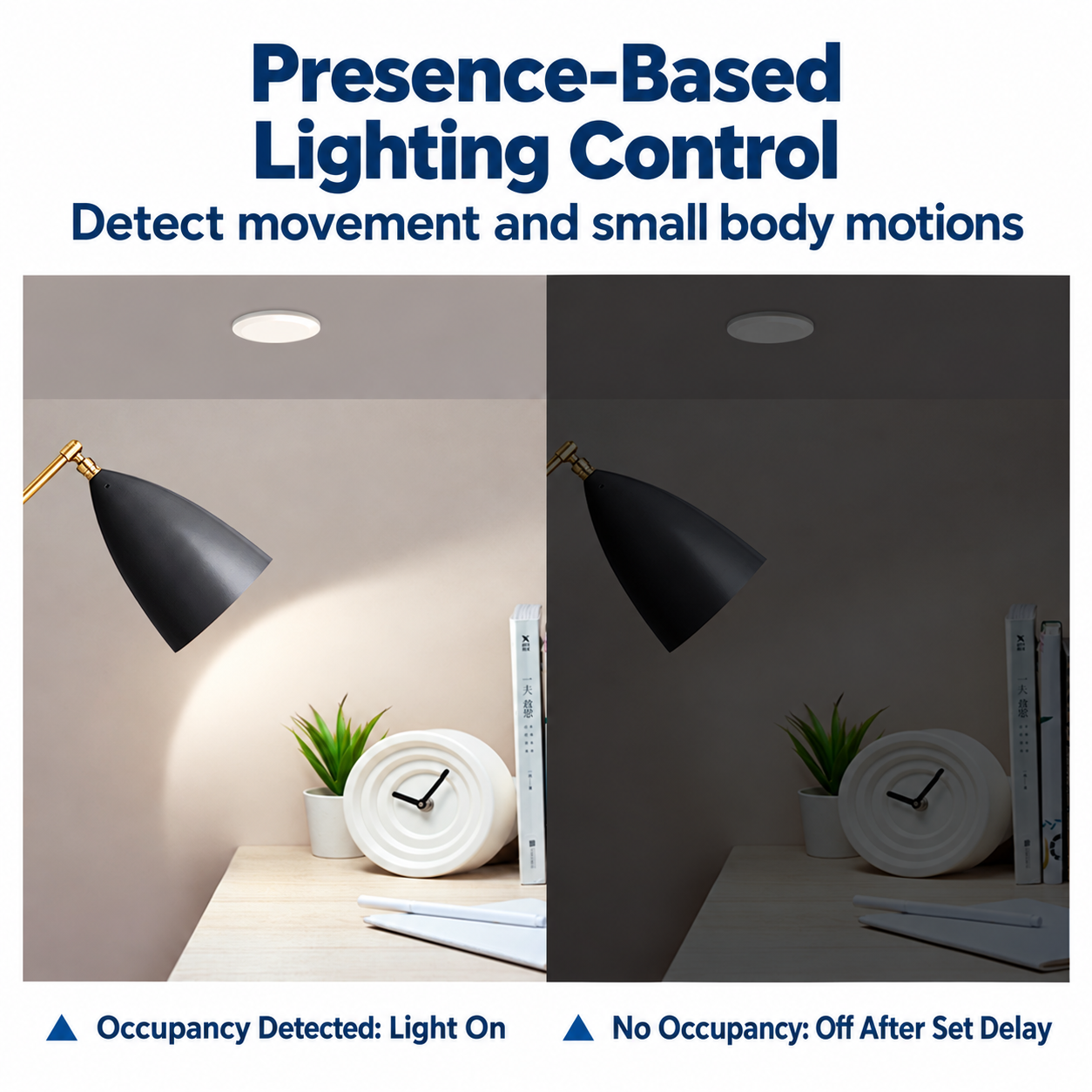
The sensor uses 24GHz radar technology to detect movement and small body movements within its configured coverage area. It keeps connected lighting on while occupancy is detected and switches it off after the selected delay when no further presence is detected.
- 24–24.25GHz radar detection.
- Standalone operation without a network connection.
- Four selectable detection sensitivity settings.
- Five selectable switch-off delays.
- Low-light or all-day activation settings.
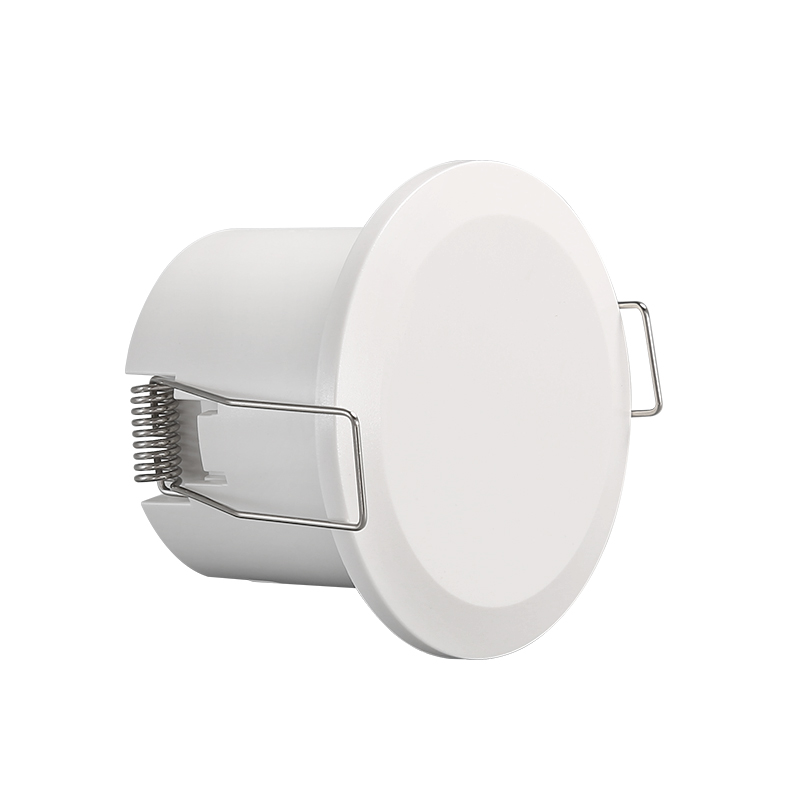
- Compact recessed design with spring clips.
- AC 90–265V, 50/60Hz power supply.
Adjustable Detection Coverage
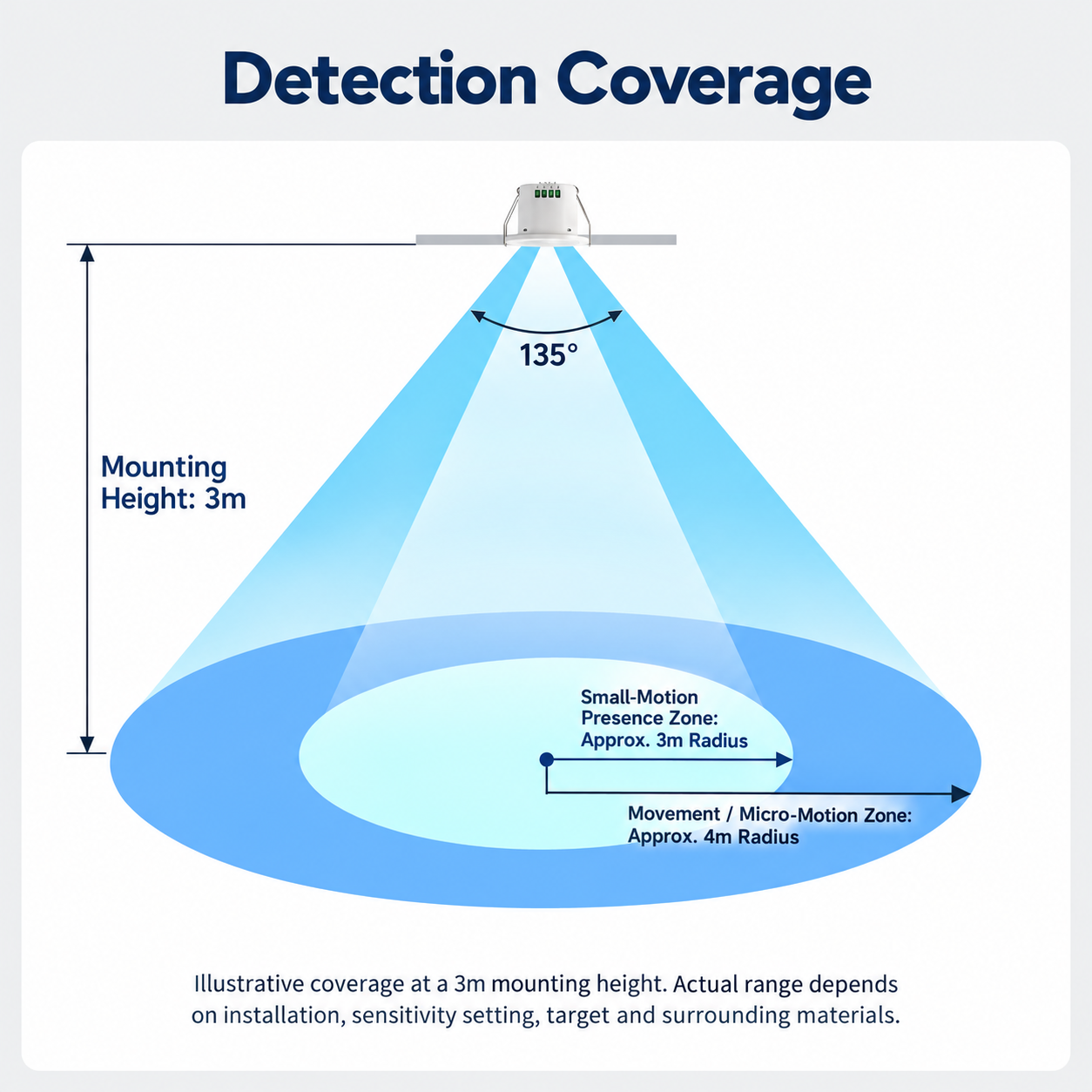
Adjust the detection sensitivity to suit the room layout and installation position. Available settings are 25%, 50%, 75% and 100%.
The coverage illustration shows a nominal 135° detection angle at a 3m ceiling height, with an inner small-motion presence zone and a wider movement detection zone. Actual coverage depends on the installation height, target movement, surrounding materials and sensitivity setting. Confirm performance at the installation site.
Wiring and Electrical Connections
The sensor requires an AC 90–265V, 50/60Hz supply and a neutral connection. Installation, wiring and configuration must be carried out by a qualified electrician with the mains supply disconnected and verified dead.
Identify each terminal using the markings on the actual product and the supplied wiring diagram. Do not identify terminals solely by wire colour or their apparent position in a photograph.
| Terminal Function | Connection |
|---|---|
| Supply Live — Input L | Connect the incoming mains live conductor to the terminal marked for live input. |
| Supply Neutral — Input N | Connect the incoming mains neutral conductor and the lamp neutral connection as shown in the supplied wiring diagram. |
| Switched Live — Light L | Connect the lamp live conductor to the sensor’s switched lighting output. |
| Additional Fire-Control Terminal | This terminal is not used in the manual’s basic lighting circuit. Obtain the manufacturer’s specific connection instructions before using it. Do not bridge it to another terminal. |
Load limits: maximum 200W for LED lighting, or maximum 500W for CFL and incandescent lighting. Confirm suitability for the connected lamps and their drivers before installation.
Installation Sequence
- Disconnect the mains supply and verify that the circuit is dead.
- Prepare a 50mm ceiling cutout and confirm adequate clearance for the sensor body and wiring.
- Make the supply and lamp connections according to the actual terminal markings and supplied wiring diagram. Maintain any protective-earth connections required by the lighting circuit.
- Set the DIP switches for the required sensitivity, switch-off delay and ambient-light activation.
- Raise the spring clips, insert the sensor into the cutout and check that it is securely retained.
- Restore power after completing the electrical checks, then test the detection area and lighting operation.
Detailed DIP-Switch Settings
The six DIP switches are divided into three independent groups: switches 1–2 control detection sensitivity, switches 3–5 control the switch-off delay, and switch 6 selects ambient-light activation.
ON means the switch is moved towards the position marked “ON” on the DIP-switch block. OFF means the opposite position; it corresponds to the dash shown in the instruction manual. Disconnect the mains supply before accessing or adjusting the switches.
Switches 1–2: Detection Sensitivity
| Sensitivity | Switch 1 | Switch 2 |
|---|---|---|
| 100% | ON | ON |
| 75% | OFF | ON |
| 50% | ON | OFF |
| 25% | OFF | OFF |
These percentages indicate sensitivity settings, not a guaranteed percentage of floor area or a fixed detection distance. Start with a setting appropriate for the room, then test and adjust on site.
- 25%: suggested starting point for rooms approximately 2m × 2m or smaller.
- 50%: suggested starting point for rooms approximately 3m × 3m.
- 75%: suggested starting point for rooms approximately 4m × 4m.
- 100%: suggested starting point for rooms approximately 5m × 5m or larger.
These room sizes are reference examples from the manual. Actual performance depends on the installation position, surrounding materials and movement inside or beyond the intended detection area.
Switches 3–5: Switch-Off Delay
Select how long the lighting remains on after the sensor stops detecting occupancy.
| Delay | Switch 3 | Switch 4 | Switch 5 |
|---|---|---|---|
| 5 seconds | ON | ON | ON |
| 30 seconds | OFF | ON | ON |
| 1 minute | ON | OFF | ON |
| 3 minutes | ON | ON | OFF |
| 5 minutes | OFF | OFF | OFF |
Only the combinations listed above are specified in the manual. Do not assume a function for unlisted combinations.
For initial setup, the manual suggests a delay of 1–3 minutes for single-person spaces and 30 seconds–1 minute for spaces used by multiple people. Adjust after testing normal occupancy and exit conditions.
Switch 6: Ambient-Light Activation
| Switch 6 | Setting | Operation |
|---|---|---|
| ON | 5 lux | Enables occupancy-triggered lighting when ambient light is below the selected low-light threshold. |
| OFF | All-day | Enables occupancy-triggered lighting regardless of ambient brightness. |
All-day mode does not mean always-on lighting. Occupancy detection and the selected switch-off delay still control the connected light.
Example Configuration
For 50% sensitivity, a 1-minute delay and all-day activation, set switches 1–6 as follows:
1: ON 2: OFF 3: ON 4: OFF 5: ON 6: OFF
This is an example, not a universal default. Verify the detection area and switch-off behaviour after installation, and reduce sensitivity if movement outside the intended area causes unwanted activation.
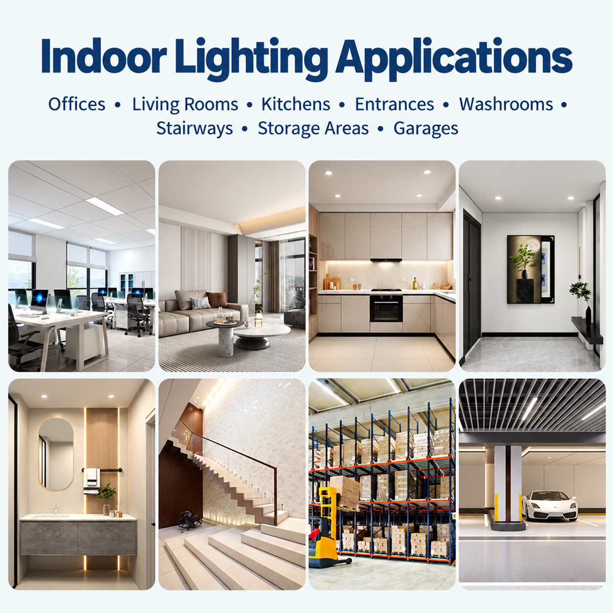
Designed for Indoor Lighting Applications
Suitable applications include offices, living rooms, kitchens, entrance areas, washrooms, stairways, storage rooms and garages. Select an installation position and sensitivity setting that match the intended detection area.
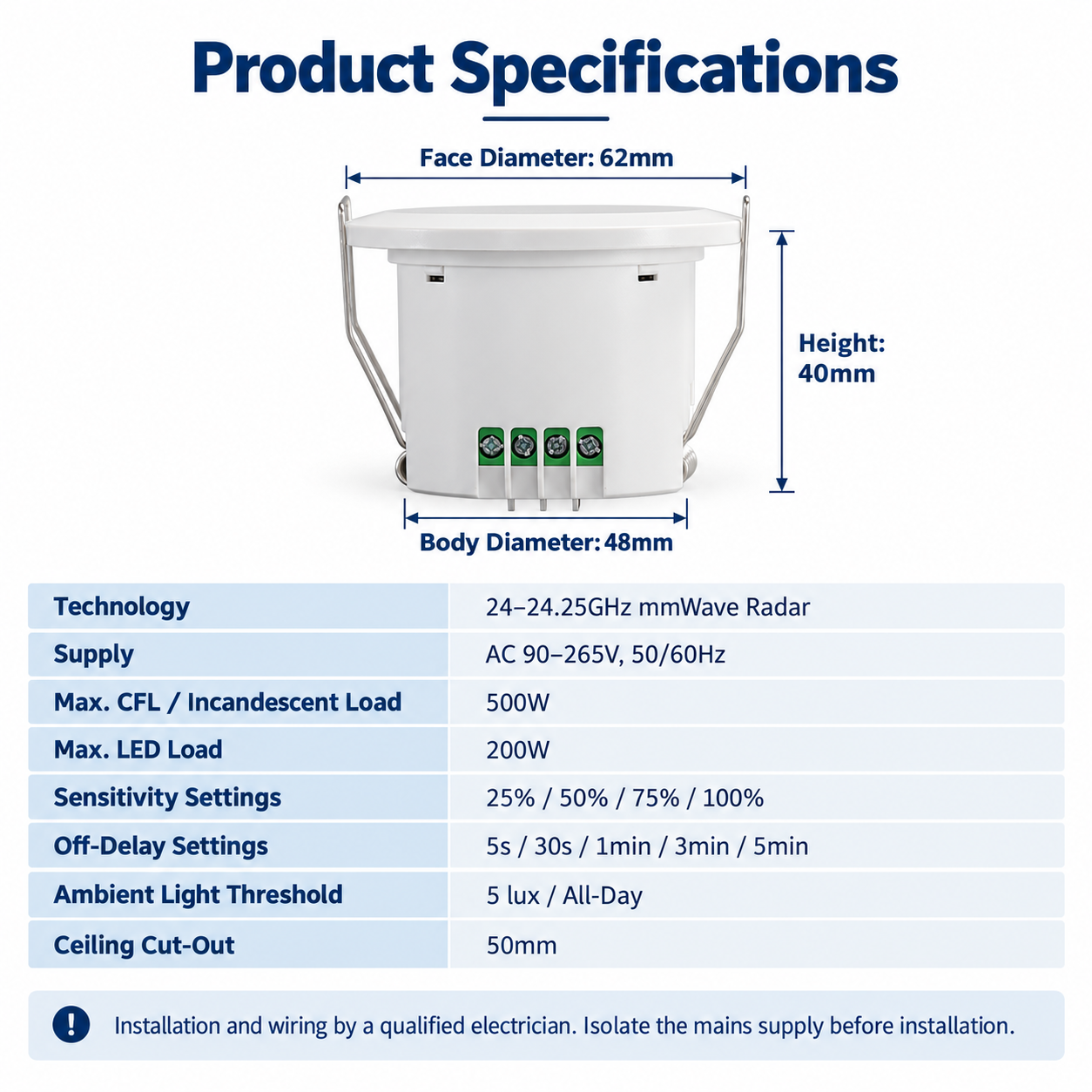
Technical Specifications
| Parameter | Specification |
|---|---|
| Product type | Recessed mmWave presence sensor switch |
| Operating frequency | 24–24.25GHz |
| Power supply | AC 90–265V, 50/60Hz |
| Maximum LED load | 200W |
| Maximum CFL / incandescent load | 500W |
| Detection sensitivity | 25% / 50% / 75% / 100% |
| Switch-off delay | 5s / 30s / 1min / 3min / 5min |
| Ambient-light setting | 5 lux / All-day |
| Face diameter | 62mm |
| Body diameter / height | 48mm / 40mm |
| Ceiling cutout diameter | 50mm |
| Mounting method | Recessed mounting with spring clips |
Installation Location and Commissioning
Use the sensor in a dry, ventilated indoor location. Check the detection area under normal room conditions before completing commissioning.
- Choose a position that covers the intended occupied area.
- Keep the sensor at least 0.5m away from wireless routers.
- Avoid nearby vibrating objects and moving fans that may cause unwanted activation.
- Keep the ambient-light sensing area clear of direct illumination that could distort its measurement.
- Consider adjacent spaces: radar signals can pass through some non-metallic materials and may detect movement beyond the intended area.
- Test sensitivity, ambient-light activation and switch-off delay after installation.
Discuss Your Presence Sensor Requirements
Contact us for product specifications, quotations and bulk-order enquiries. Please include your intended application, connected lighting load, order quantity and destination market so we can discuss the appropriate configuration.
Email: services@szhhlight.com
WhatsApp: +86 180 8889 8360